Difference between revisions of "Muonpi board"
Jump to navigation
Jump to search
| Line 1: | Line 1: | ||
| + | The MuonPi board is designed as plug-on board for the Raspberry Pi B+ in a form factor conforming with the [https://github.com/raspberrypi/hats RPi HAT specifications]. | ||
| + | |||
== Functional Description == | == Functional Description == | ||
| − | The MuonPi board | + | The MuonPi board implements following functionalities: |
| + | * Two input channels | ||
| + | * Supply voltage for remote powering the [[Preamp|preamplifier]] through the signal line: The voltage can be switched on/off through a GPIO signal (individually for the two channels). It includes overcurrent and overtemperature shutdown and a fault signal. | ||
| + | * Bias voltage supply for the SiPM sensor and bias voltage/current supervision. A DC/DC converter generates the required reverse biasing voltage from the RPi 5V rail. The voltage can be switched on/off through a GPIO signal. Actual bias voltage and current are measured through the on-board ADC. The voltage can be controled through the on-board DAC (not in HW version 2). | ||
| + | * Optional inverter for the two signal inputs (mounting option) in case negative signals are presented to the board | ||
| + | * Threshold discriminators with adjustable thresholds (DAC channels 1 and 2) in the range from 0.5 mV to 3V. The discriminator outputs are LVCMOS signals with a length of ~100 ns. | ||
| + | |||
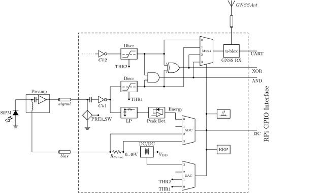
[[File:MuonPi-blockscheme.png|640px|MuonPi functional block schematic]] | [[File:MuonPi-blockscheme.png|640px|MuonPi functional block schematic]] | ||
Revision as of 15:27, 15 April 2020
The MuonPi board is designed as plug-on board for the Raspberry Pi B+ in a form factor conforming with the RPi HAT specifications.
Functional Description
The MuonPi board implements following functionalities:
- Two input channels
- Supply voltage for remote powering the preamplifier through the signal line: The voltage can be switched on/off through a GPIO signal (individually for the two channels). It includes overcurrent and overtemperature shutdown and a fault signal.
- Bias voltage supply for the SiPM sensor and bias voltage/current supervision. A DC/DC converter generates the required reverse biasing voltage from the RPi 5V rail. The voltage can be switched on/off through a GPIO signal. Actual bias voltage and current are measured through the on-board ADC. The voltage can be controled through the on-board DAC (not in HW version 2).
- Optional inverter for the two signal inputs (mounting option) in case negative signals are presented to the board
- Threshold discriminators with adjustable thresholds (DAC channels 1 and 2) in the range from 0.5 mV to 3V. The discriminator outputs are LVCMOS signals with a length of ~100 ns.
