Preamplifier
Jump to navigation
Jump to search
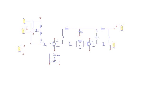
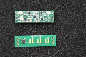
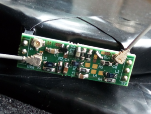
The preamplifier should increase the SiPM's weak pulse amplitude by ca. 20dB and must be located as close as possible to the SiPM. Therefore, a plug-on PCB for the SiPM board with the same form factor was designed, which shall be as versatile as possible in order to adapt for different read-out concepts with following properties:
- supply of the SiPM bias voltage through the preamp including bias filter
- AC-coupling of the preamp input
- based on low-noise Infineon MMIC BGA614
- mounting option for one (default, positive output) or two MMIC stages (negative output)
- options for preamp voltage supply (+5V): via separate connector (J2) or remote powering via output signal (default)
For the different operation modes, following mounting options are offered (unmentioned components are as indicated in schematics or as in the default option):
Default (single-stage, remote powering)
- do not mount: IC2, C5, C6, L4, R5, C7, J2, J5
- mount: R7 (0R), R6 (0R), connect IC2 pins 1 to 3 (e.g. with edge mounted 0R resistor)
Dual-stage
- mount: IC2, R6/C7 = pole-zero-cancellation network (e.g. 47R/22p)
Separate power supply connection
- do not mount: L3
- mount: J2
Floating bias voltage supply (galvanically isolated from signal GND)
- dnm: R7
- mount C5, C6
General purpose 50Ω RF amplifier (no SiPM, signal input via u.Fl socket J5)
- dnm: J1, J3, R1, R2, L2
- mount: J5


