SiPM board
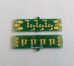
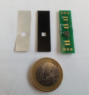
The SiPM board is a printed circuit board (PCB) designed to dock and process the signal from the SiPM-scintillator coupling into a readout. Ideally no information such as timing from the scintillator should be lost, and the signal could be amplified/ processed with the board. In some applications involving significant temperature fluctuations, a compensator could also be built into the board. For the Muonpi project, the board should just be able to dock the SiPM-scintillator coupling to the readout.
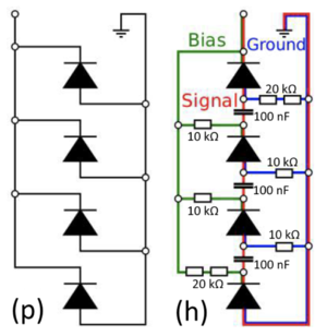
The circuit configuration of the PCB varies depending on the number of SiPM's it needs to accommodate. For housing a single Ketek PM3350-EB SiPM the configuration is to just connect it with ground and readout/ bias. However, for connecting multiple SiPM's there are two possible configurations: parallel (p) and hybrid (h) configuration as illustrated below.

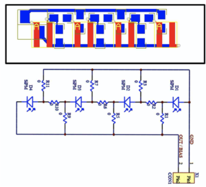
Both configurations are quite similar in term of performance, with the hybrid configuration having a slightly faster rising edge (by a few ns [2]). The signal amplitude for the hybrid configuration decreases by a factor of where N the number of SiPM, whereas the signal amplitude does not change for parallel configuration. However, the timing of the parallel configuration also decreases with the number of connected SiPM's; hence, for applications that are very time sensitive, the hybrid configuration might be necessary. Moreover, the hybrid configuration has more complexity, which might make the configuration more expensive to produce. Therefore for simplicity, the Muonpi project uses the parallel configuration. It keeps the simplicity while giving the option for adding SiPM further down the road. The schematic of the SiPM board for the Muon Pi project is shown below.

- ↑ [S. Zimmermann. The panda barrel-tof detector. DPG-Frühjahrstagung, Münster. Austrian Academy of Sciences, Stefan Meyer Insitute for Subatomic Physics, 28th of March, 2017.]
- ↑ [Nies, L., Zaunick, H. G., & Brinkmann, K-. T.. Development of a SiPM-based readout-module for the characterization of various scintillator materials. arXiv. (2018).
- ↑ [L. Nies, “Development of a sipm-based readout-module for the characterization of various scintillation materials (bachelor’s thesis),” (August 2017).]


