Difference between revisions of "Preamplifier"
Jump to navigation
Jump to search
| Line 2: | Line 2: | ||
* supply of the SiPM bias voltage through the preamp including bias filter | * supply of the SiPM bias voltage through the preamp including bias filter | ||
* AC-coupling of the preamp input | * AC-coupling of the preamp input | ||
| − | * based on low-noise MMIC [https://www.infineon.com/cms/en/product/rf-wireless-control/low-noise-amplifier-lna-ics/general-purpose-lnas/bga614/ BGA614] | + | * based on low-noise Infineon MMIC [https://www.infineon.com/cms/en/product/rf-wireless-control/low-noise-amplifier-lna-ics/general-purpose-lnas/bga614/ BGA614] |
* mounting option for one or two MMIC stages | * mounting option for one or two MMIC stages | ||
| + | * options for preamp voltage supply: via separate connector or through remote powering via output cable | ||
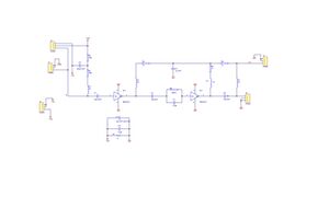
[[File:Preamp V3-1.jpg|thumb|left|Preamplifier schematic]] | [[File:Preamp V3-1.jpg|thumb|left|Preamplifier schematic]] | ||
Revision as of 22:33, 4 April 2020
The preamplifier should increase the SiPM's weak pulse amplitude by ca. 20dB and must be located as close as possible to the SiPM. Therefore, a plug-on PCB for the SiPM board with the same form factor was designed, which shall be as versatile as possible in order to adapt for different read-out concepts with following properties:
- supply of the SiPM bias voltage through the preamp including bias filter
- AC-coupling of the preamp input
- based on low-noise Infineon MMIC BGA614
- mounting option for one or two MMIC stages
- options for preamp voltage supply: via separate connector or through remote powering via output cable
