The Detector
The current detector design is based on a plastic scintillator, wrapped in different types of foil, and a Silicon Photomultiplier for the collection of scintillation light. In this article, the assembly of a detector module will be explained.
Contents
How to build a muon detector
Material List
Independent of the size and shape of the scintillator the following materials and tools are used for building a scintillator detector:

- Kapton stencil
- Teflon foil
- Aluminum foil
- Reflective foil
- Black tape
- Pond liner (thick black foil)
- Optical grease
- Scintillator
- Silicon Photomultiplier (SiPM) on PCB chip
- Preamplifier
- Scalpel
- Scissors
- Tweezer
Assembly Steps
- Cutting the scintillator: In the case for the MuonPi detectors the scintillators are provided as plates of 10x250x250 mm^3. Depending on the desired geometry, the scintillators are cut with a circular saw to fit the design. Afterwards, all edges are polished.
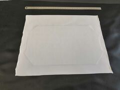
- Cutting the Kapton stencil: The stencil is used as a template and carrier for cutting the thin Teflon and aluminum foil. It is usually cut in the same base shape as the scintillator but slightly larger to accommodate the edges of the scintillator. The stencil is reusable and only has to be crafted once.
- Cutting and wrapping the Teflon foil: The thin layer of Teflon foil is unrolled and laid out on top of the stencil, removing all wrinkles carefully. Guided by the outlines of the stencil, the Teflon foil is cut using a sharp scalpel. Depending on the desired thickness of the Teflon on the scintillator, this step is repeated several times. Finally, the scintillator is placed with its top face centered on top of the Teflon cut-out and the surplus of Teflon is carefully folded upwards to cover the edges of the scintillator. Now the scintillator can be flipped such that the top faces downwards and the stencil is carefully removed. To cover the other face, this step is repeated.
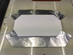
- Cutting and wrapping the aluminum foil: The aluminum foil, while using the stencil, is prepared and attached to the scintillator in a similar fashion. The foil is fixed with reflective tape.
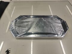
- Cutting and taping the pond liner: A layer of thick pond liner is used to cover both faces of the scintillator. For this, the base shape of the scintillator is used to cut the liner. Using double-sided tape, the liner is glued on both faces.
- Taping the edges: Black tape is used to cover all left-over uncovered spots of the scintillator apart from the light-collection faces. Now the scintillator is ready to be coupled with the photo-detector.
- Attaching the SiPM: The SiPM sitting on its PCB chip and equipped with a reflective mask is covered with a small amount of optical grease and is pressed against the light collection surface. While maintaining the pressure, the chip is fixed to the scintillator with black tape. Since the preamplifier and the SiPM are designed modular, the preamplifier chip can be plugged on top of the SiPM chip.
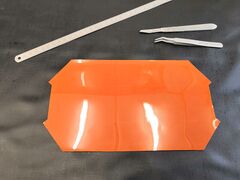
Kapton stencil and tools
Teflon foil outlined on stencil
Prepared aluminum foil ready for assembly
Both types of foil fixed with reflective tape

Layer of pond liner added


Detector specifications
Our detectors come in many different geometries and configurations.
Detector geometry
Several different detector geometries can be build from the raw scintillator plates provided by our supplier Eljen. The uncut scintillator plates have a dimension of 10x250x250 mm^3.
The original
The original detector geometry is inspired by